graphics-snippets
- Model, View, Projection and Depth
Model, View, Projection and Depth
In a rendering, each mesh of the scene usually is transformed by the model matrix, the view matrix and the projection matrix. Finally the projected scene is mapped to the viewport.
The projection, view and model matrix interact together to present the objects (meshes) of a scene on the viewport. The model matrix defines the position orientation and scale of a single object (mesh) in the world space of the scene. The view matrix defines the position and viewing direction of the observer (viewer) within the scene. The projection matrix defines the area (volume) with respect to the observer (viewer) which is projected onto the viewport.
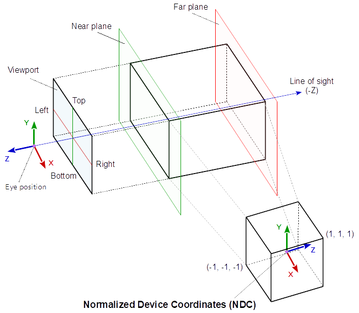
At orthographic projection, this area (volume) is defined by 6 distances (left, right, bottom, top, near and far) to the viewer’s position. If the left, bottom and near distance are negative and the right, top and far distance are positive (as in normalized device space), this can be imagined as box around the viewer. All the objects (meshes) which are in the space (volume) are “visible” on the viewport. All the objects (meshes) which are out (or partly out) of this space are clipped at the borders of the volume. This means at orthographic projection, the objects “behind” the viewer are possibly “visible”. This may seem unnatural, but this is how orthographic projection works.
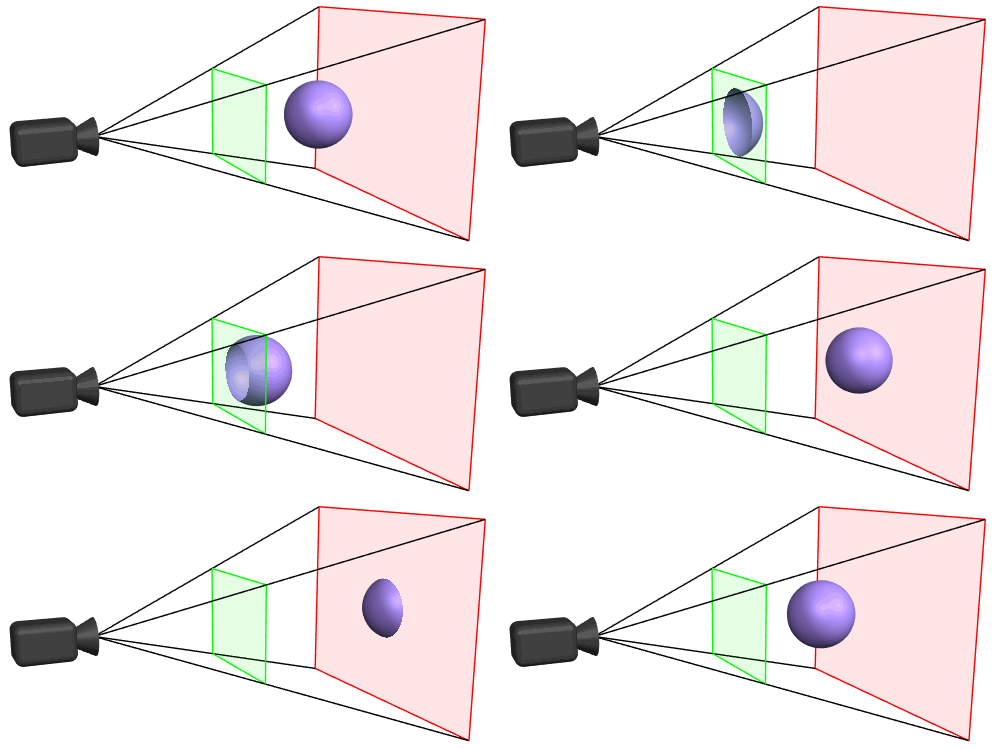
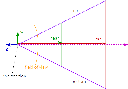
In perspective projection the viewing volume is a frustum (a truncated pyramid), where the top of the pyramid is the viewing position. The direction of view (line of sight) and the near and the far distance define the planes which truncated the pyramid to a frustum (the direction of view is the normal vector of this planes). The left, right, bottom, top distance define the distance from the intersection of the line of sight and the near plane, with the side faces of the frustum (on the near plane). The geometry is projected onto the viewport along the ray running through the camera position. This causes that the scene looks like, as it would be seen from of a pinhole camera.
One of the most common mistakes, when an object is not visible on the viewport (screen is all “black”), is that the mesh is not within the view volume which is defined by the projection and view matrix.
Coordinate Systems
Model coordinates (Object coordinates)
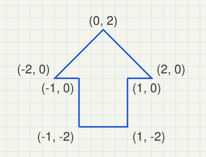
The model space is the coordinates system, which is used to define or modulate a mesh. The vertex coordinates are defined in model space.
e.g.:
World coordinates
The world space is the coordinate system of the scene. Different models (objects) can be placed multiple times in the world space to form a scene, in together.
Model matrix
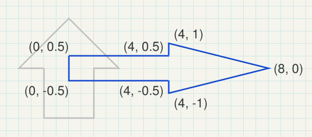
The model matrix defines the location, orientation and the relative size of a model (object, mesh) in the scene. The model matrix transforms the vertex positions of a single mesh to world space for a single specific positioning. There are different model matrices, one for each combination of a model (object) and a location of the object in the world space.
The model matrix looks like this:
( X-axis.x, X-axis.y, X-axis.z, 0 )
( Y-axis.x, Y-axis.y, Y-axis.z, 0 )
( Z-axis.x, Z-axis.y, Z-axis.z, 0 )
( trans.x,  trans.y,  trans.z,  1 )
e.g.:
(  0.0, -0.5,  0.0,  0.0 )
(  2.0,  0.0,  0.0,  0.0 )
(  0.0,  0.0,  1.0,  0.0 )
(  0.4,  0.0,  0.0,  1.0 )
View space (Eye coordinates)
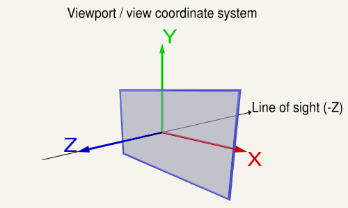
The view space is the local system which is defined by the point of view onto the scene.
The position of the view, the line of sight and the upwards direction of the view, define a coordinate system relative to the world coordinate system. The objects of a scene have to be drawn in relation to the view coordinate system, to be “seen” from the viewing position. The inverse matrix of the view coordinate system is named the view matrix. This matrix transforms from world coordinates to view coordinates.
In general world coordinates and view coordinates are Cartesian coordinates
View matrix
The view coordinates system describes the direction and position from which the scene is looked at. The view matrix transforms from the world space to the view (eye) space.
If the coordinate system of the view space is a Right-handed system, where the X-axis points to the right and the Y-axis points up, then the Z-axis points against the line of sight (Note in a right hand system the Z-Axis is the cross product of the X-Axis and the Y-Axis).
Clip coordinates
Clip space coordinates are Homogeneous coordinates. In clip space the clipping of the scene is performed.
A point is in clip space if the x, y and z components are in the range defined by the inverted w component and the w component of the homogeneous coordinates of the point:
-w <= x, y, z <= w.
Projection matrix
The projection matrix describes the mapping from 3D points of a scene, to 2D points of the viewport. The projection matrix transforms from view space to the clip space. The coordinates in the clip space are transformed to the normalized device coordinates (NDC) in the range (-1, -1, -1) to (1, 1, 1) by dividing with the w component of the clip coordinates.
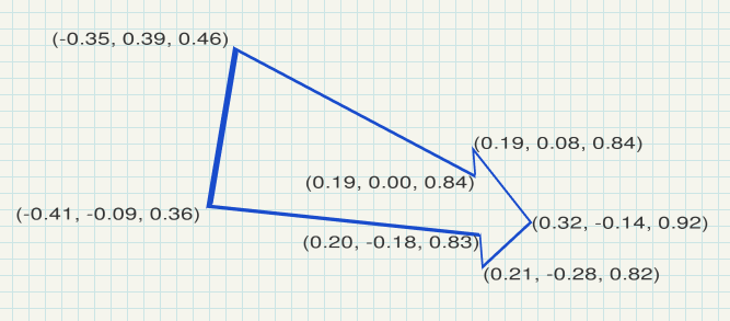
e.g.:
look at: eye position (2.5, -1.5, 3.5), center (2, 0, 0), up vector (0, 1, 0)
perspective projection: field of view (y) of 100 degrees, near plane at 0.1, far plane at 20.0
Normalized device coordinates
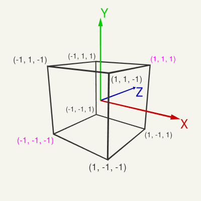
The normalized device space is a cube, with right, bottom, front of (-1, -1, -1) and a left, top, back of (1, 1, 1).
The normalized device coordinates are the clip space coordinates divide by the w component of the clip coordinates. This is called Perspective divide
Window coordinates (Screen coordinates)
The window coordinates are the coordinates of the viewport rectangle. The window coordinates are decisive for the rasterization process.
Viewport and depth range
The normalized device coordinates are linearly mapped to the viewport rectangle (Window Coordinates / Screen Coordinates) and to the depth for the depth buffer.
The viewport rectangle is defined by glViewport. The depth range is set by glDepthRange and is by default [0, 1].
See also: OpenGL Transformation
View
On the viewport the X-axis points to the left, the Y-axis up and the Z-axis against the line of sight (Note in a c the Z-Axis is the cross product of the X-Axis and the Y-Axis).
The code below defines a matrix that exactly encapsulates the steps necessary to calculate a look at the scene:
- Converting model coordinates into view system coordinates.
- Rotation, to look in the direction of the view.
- Movement to the eye position.
The following code does the same as gluLookAt or glm::lookAt does:
using TVec3  = std::array< float, 3 >;
using TVec4  = std::array< float, 4 >;
using TMat44 = std::array< TVec4, 4 >;

TVec3 Cross( TVec3 a, TVec3 b ) { return { a[1] * b[2] - a[2] * b[1], a[2] * b[0] - a[0] * b[2], a[0] * b[1] - a[1] * b[0] }; }
float Dot( TVec3 a, TVec3 b ) { return a[0]*b[0] + a[1]*b[1] + a[2]*b[2]; }
void Normalize( TVec3 & v )
{
    float len = sqrt( v[0] * v[0] + v[1] * v[1] + v[2] * v[2] );
    v[0] /= len; v[1] /= len; v[2] /= len;
}

TMat44 Camera::LookAt( const TVec3 &pos, const TVec3 &target, const TVec3 &up )
{
    TVec3 mz = { pos[0] - target[0], pos[1] - target[1], pos[2] - target[2] };
    Normalize( mz );
    TVec3 my = { up[0], up[1], up[2] };
    TVec3 mx = Cross( my, mz );
    Normalize( mx );
    my = Cross( mz, mx );

    TMat44 v{
        TVec4{ mx[0], my[0], mz[0], 0.0f },
        TVec4{ mx[1], my[1], mz[1], 0.0f },
        TVec4{ mx[2], my[2], mz[2], 0.0f },
        TVec4{ Dot(mx, pos), Dot(my, pos), -Dot(mz, pos), 1.0f }
    };

    return v;
}
Euclidean length of a vector:
def length(v):
    return math.sqrt(v[0]*v[0]+v[1]*v[1]+v[2]*v[2])
def normalize(v):
    l = length(v)
    return [v[0]/l, v[1]/l, v[2]/l]
def dot(v0, v1):
    return v0[0]*v1[0]+v0[1]*v1[1]+v0[2]*v1[2]
def cross(v0, v1):
    return [
        v0[1]*v1[2]-v1[1]*v0[2],
        v0[2]*v1[0]-v1[2]*v0[0],
        v0[0]*v1[1]-v1[0]*v0[1]]
The following code does the same as gluLookAt or glm::lookAt does:
The parameter eye is the point of view, target is the point which is looked at and up is the upwards direction.
def m3dLookAt(eye, center, up):
    mz = normalize( (eye[0]-target[0], eye[1]-target[1], eye[2]-target[2]) ) # inverse line of sight
    mx = normalize( cross( up, mz ) )
    my = normalize( cross( mz, mx ) )
    tx =  dot( mx, eye )
    ty =  dot( my, eye )
    tz = -dot( mz, eye )
    return np.array([mx[0], my[0], mz[0], 0, mx[1], my[1], mz[1], 0, mx[2], my[2], mz[2], 0, tx, ty, tz, 1])
Use it like this:
view_position = [0, 0, 20]
view_matrix = m3dLookAt(view_position, [0, 0, 0], [0, 1, 0])
understanding camera translation in GLM- openGL
glm::lookAt defines the view matrix. The view matrix transforms vertex coordinates from world space to view space.
eye, center and up are positions respectively vectors in world space, which define the the position and orientation of the camera in world space. eye, center and up define the view space. If you would setup a matrix by this vectors, then the matrix would transform from view space to world space.
Since the view matrix has to do the opposite (world space -> view space), the view matrix is the inverse matrix of that matrix which is defined by eye, center and up. glm::lookAt is a optimized algorithm for computing an inverse matrix in this spacial case.
Note s, u, f are transposed when they are assigned to the matrix.
The translation of the inverse matrix is not the negative translation of the matrix. The translation of the inverse matrix has to consider the orientation (rotation). Because of that the translation vector has to be rotated. The rotation of a (3d) vector by a 3x3 Rotation matrix can be computed by (is the same as) the 3 Dot products of the axis vectors and the direction vector. (s, u, f) define a 3x3 rotation matrix and eye is transformed by this matrix.
What the code actually dose is to concatenate a rotation by transposed (s, u, f) and a translation by -eye (very simplified pseudo code):
viewmatrix = transpose(rotation(s, u, f)) * translation(-eye)
Projection
The projection matrix describes the mapping from 3D points of the view on a scene, to 2D points on the viewport. It transforms from eye space to the clip space, and the coordinates in the clip space are transformed to the normalized device coordinates (NDC) by dividing with the w component of the clip coordinates. The NDC are in range (-1,-1,-1) to (1,1,1).
Every geometry which is out of the clip space is clipped.
But, if the w component is negative, then the vertex is clipped. Because the condition for a homogeneous coordinate to be in clip space is
-w <= x, y, z <= w.
If w = -1 this would mean:
1 <= x, y, z <= -1.
and that can never be fulfilled.
Orthographic Clip Space
Perspective Clip Space
The objects between the near plane and the far plane of the camera frustum are mapped to the range (-1, 1) of the NDC.
The viewing frustum is limited by the near and far plane. The geometry is clipped at the 6 planes of the frustum.
Depth
Whether the depth (gl_FragCoord.z and gl_FragDepth) is linear mapped or not depends on, the projection matrix.
While for Orthographic Projection the depth is linear, for Perspective Projection it is not linear.
In general, the depth (gl_FragCoord.z and gl_FragDepth) is calculated as follows:
float ndc_depth = clip_space_pos.z / clip_space_pos.w;
float depth = (((farZ-nearZ) * ndc_depth) + nearZ + farZ) / 2.0;
Orthographic Projection
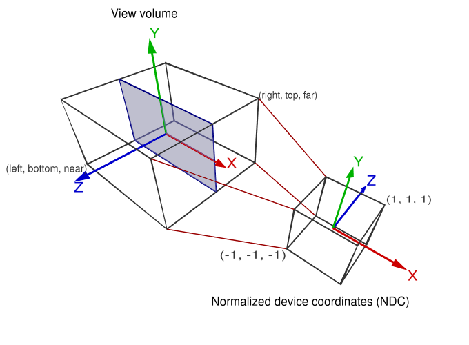
When using Orthographic Projection, the view space coordinates are mapped linearly to the clip space coordinates. The clip space coordinates are equal to the normalized device coordinates, because the w component is 1 (for a cartesian input coordinate).
The viewing volume is defined by 6 distances (left, right, bottom, top, near, far). The values for left, right, bottom, top, near and far define a cuboid (box). All of the geometry that is within the volume of the box is projected onto the two-dimensional viewport and is “visible”. All geometry that is outside this volume is clipped.
If you want to use orthographic projection, you need to define the area (cuboid volume) of your scene that you want to show in the viewport. This area indicates the 6 distances for the orthographic projection. If your viewport is rectangular and you want to keep the aspect ratio, the xy plane of the viewing volume volume must also be rectangular. The ratio of the xy plane must match the ratio of the viewport.
Orthographic Projection Matrix:
r = right, l = left, b = bottom, t = top, n = near, f = far

X:    2/(r-l)         0               0               0
y:    0               2/(t-b)         0               0
z:    0               0               -2/(f-n)        0
t:    -(r+l)/(r-l)    -(t+b)/(t-b)    -(f+n)/(f-n)    1
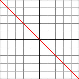
In Orthographic Projection, the Z component is calculated by the linear function:
z_ndc = z_eye * -2/(f-n) - (f+n)/(f-n)
Perspective Projection
In perspective projection, the projection matrix describes the mapping of 3D points in the world, as seen from a pinhole camera, onto 2D points in the viewport. The eye space coordinates in the camera frustum (a truncated pyramid) are mapped to a cube (the normalized device coordinates).
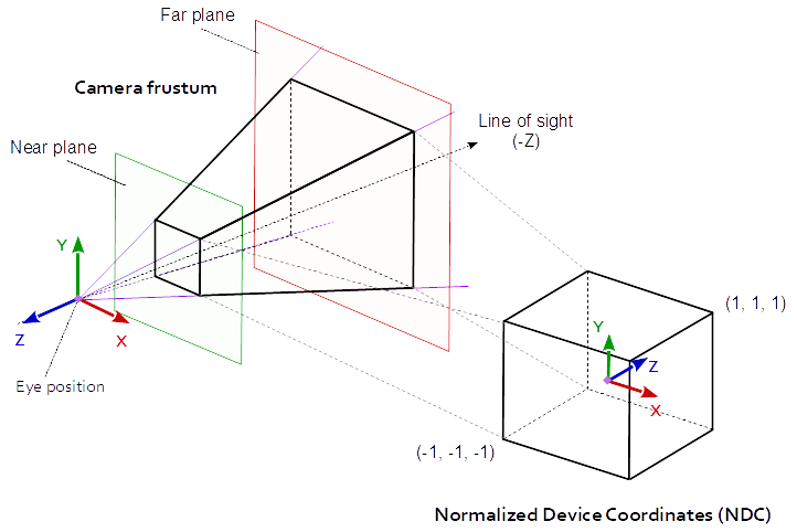
A perspective projection matrix can be defined by a frustum.
The distances left, right, bottom and top, are the distances from the center of the view to the side faces of the frustum, on the near plane. near and far specify the distances to the near and far plane of the frustum.
r = right, l = left, b = bottom, t = top, n = near, f = far

x:    2*n/(r-l)      0              0                0
y:    0              2*n/(t-b)      0                0
z:    (r+l)/(r-l)    (t+b)/(t-b)    -(f+n)/(f-n)    -1
t:    0              0              -2*f*n/(f-n)     0
If the projection is symmetrical and the line of sight is the axis of symmetry of the frustum, the matrix can be simplified:
a  = w / h
ta = tan( fov_y / 2 );

2 * n / (r-l) = 1 / (ta * a)
2 * n / (t-b) = 1 / ta
(r+l)/(r-l)   = 0
(t+b)/(t-b)   = 0
The symmetrically perspective projection matrix is:
x:    1/(ta*a)  0      0              0
y:    0         1/ta   0              0
z:    0         0     -(f+n)/(f-n)   -1
t:    0         0     -2*f*n/(f-n)    0
The following function will calculate the same projection matrix as gluPerspective does:
#include <array>

const float cPI = 3.14159265f;
float ToRad( float deg ) { return deg * cPI / 180.0f; }

using TVec4  = std::array< float, 4 >;
using TMat44 = std::array< TVec4, 4 >;

TMat44 Perspective( float fov_y, float aspect )
{
    float fn = far + near
    float f_n = far - near;
    float r = aspect;
    float t = 1.0f / tan( ToRad( fov_y ) / 2.0f );

    return TMat44{
        TVec4{ t / r, 0.0f,  0.0f,                 0.0f },
        TVec4{ 0.0f,  t,     0.0f,                 0.0f },
        TVec4{ 0.0f,  0.0f, -fn / f_n,            -1.0f},
        TVec4{ 0.0f,  0.0f, -2.0f*far*near / f_n,  0.0f }
    };
}
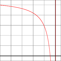
At Perspective Projection, the Z component is calculated by the rational function:
z_ndc = ( -z_eye * (f+n)/(f-n) - 2*f*n/(f-n) ) / -z_eye
What the perspective projection does
-
The projection matrix transforms from view space to clip space, respectively normalized device space
-
The perspective projection describes the mapping from 3D points in the world as they are seen from of a pinhole camera, to 2D points of the viewport.
But what does that mean?
Imagine a perfect cube, which is looked at with one eye. If the cube is fare away, it appears small. If the cube is close to the eye it appears large or is even not visible completely.
The perspective projection reflects this behavior.
Send rays from the eye to all directions of the range of vision. Close to the eye, the field, which is penetrated by the rays, is small. As the distance increases, the field becomes larger, square to the distance. The conical volume, which is permeated by the rays, is the view volume.
In computer graphics this volume is not a cone, its base is a rectangle, because of the rectangular viewport. Further there is a near and a far plane, which limits the view volume in its range. This is because of the limited number range, that can be represented by digital computer technology. This truncated pyramid is the perspective view frustum.
The single rays are projected on the pixel of the viewport. Imagine a panel with a hole matrix, as many holes in a row, as pixel in the width of the view and as many holes in a column as pixel in the height of the view. Rays sent from the eye through each hole of the raster, represents the mapping of rays to the pixels on the viewport. The color of the first objected which is hit by a ray is placed at the pixel, which is represented by the ray.
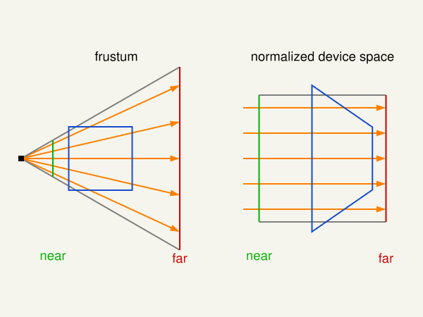
At the left side, the following image shows a cube which is looked at from a eye position and the view frustum. The right part of the image shows the perspective distortion, caused by the projection on the viewport. The plane of the cube which is closer to the view position seems to be larger, than the plane which is further away. The front top and bottom edge of the cube are clipped, because they are not in the view volume and not visible on the viewport.
Relation between z distance and depth
The depth of a geometry at perspective projection is
depth = (1/z - 1/n) / (1/f - 1/n)
where z is the distance to the point of view, n is the distance to the near plane and f is the distance to the far plane of the Viewing frustum.
For the depth we are just interested in the z and w component. For an input vertex (x_eye, y_eye, z_eye, w_eye), the clip space z_clip and w_clip components are computed by:
z_clip = C * z_eye + D * w_eye
w_clip = -z_eye
where (from perspective projection matrix)
C = -(f+n) / (f-n)
D = -2fn / (f-n)
The normalized device space z coordinate is computed by a Perspective divide
z_ndc = z_clip / w_clip
The normalized device space z coordinate is mapped to the depth range [a, b] (see glDepthRange):
depth = a + (a-b) * (z_ndc+1)/2
When we assume tha the depth range is [0, 1] and the input vertex is a Cartesian coordinate (x_eye, y_eye, z_eye, 1), this leads to the following:
             z_eye * -(f+n) / (f-n)  +  -2fn / (f-n)
depth  =  (------------------------------------------ + 1) / 2
                          -z_eye
And can be transformed
             -z_eye * (f+n)  -  2fn
depth  =  (-------------------------- + 1) / 2
               -z_eye  *  (f-n)
             -z_eye * (f+n)  -  2fn  +  -z_eye * (f-n)
depth  =  ---------------------------------------------
                      -z_eye  *  (f-n)  * 2
             -z_eye * (f+n+f-n)  -  2fn
depth  =  -------------------------------
               -z_eye  *  (f-n)  * 2
             -z_eye * f  -  fn           -f (n + z_eye)
depth  =  -----------------------   =   ----------------
               -z_eye * (f-n)             z_eye (n - f)
Since the view space z axis points out of the viewport, the z distance from the point of view to the vertex is z = -z_eye. This leads to:
          f (n - z)        1/z - 1/n
depth  =  -----------  =  -----------
          z (n - f)        1/f - 1/n
Depth buffer
Since the normalized device coordinates are in range (-1,-1,-1) to (1,1,1) the Z-coordinate has to be mapped to the depth buffer the range [0,1]:
depth = (z_ndc + 1) / 2
How the Z component of the normalized device space is mapped to the depth value, can in OpenGL be defined by the function glDepthRange. Usually the range is [0, 1], from the near plane to the far plane.
Note, in the fragment shader, the built in input variable gl_FragCoord is available, that contains the window relative coordinate (x, y, z, 1/w) values for the fragment.
The z component contains the depth value, that would be written to gl_FragDepth(except the shader code contains explicit writing to it) and is finally the value stored in th depth buffer.
gl_FragCoord may be redeclared with the additional layout qualifier identifiers origin_upper_left or pixel_center_integer. By default, gl_FragCoord assumes a lower-left origin for window coordinates and assumes pixel centers are located at half-pixel centers. For example, the (x, y) location (0.5, 0.5) is returned for the lower-left-most pixel in a window. The origin of gl_FragCoord may be changed by redeclaring gl_FragCoord with the origin_upper_left identifier.
Unproject
To convert form the depth of the depth buffer to the original Z-coordinate, the projection (Orthographic or Perspective), and the near plane and far plane has to be known.
In the following is assumed that the depth range is in [0, 1] and depth is a value in this range:
Unproject - Orthographic Projection
n = near, f = far
z_eye = depth * (f-n) + n;

z_linear = z_eye
Unproject - Perspective Projection
n = near, f = far
z_ndc = 2 * depth - 1.0;
z_eye = 2 * n * f / (f + n - z_ndc * (f - n));
If the perspective projection matrix is known this can be done as follows:
A = prj_mat[2][2]
B = prj_mat[3][2]
z_eye = B / (A + z_ndc)
Perspective Projection - Linearized depth
Convert the depth value or the normalized device z component to a linear value in the range [0.0, 1.0] where 0.0 is near and 1.0 is far.
How To Linearize the Depth Value
Linear Depth
From linear -> non-linear depth values
z_linear = (z_eye - n) / (f - n)
Very good approximation for small near values:
z_linear = 2 * n / (f + n - z_ndc * (f - n)) - n) / (f-n)
Exact calculation:
z_linear = (2 * n * f / (f + n - z_ndc * (f - n)) - n) / (f-n)
The relation between the projected area in view space and the Z coordinate of the view space is linear. It depends on the field of view angle and the aspect ratio.
A projected size in normalized device space can be transformed to a size in view space by:
aspect = w / h
tanFov = tan(fov_y / 2.0) * 2.0;

size_x = ndc_size_x * z_eye * tanFov * aspect;
size_y = ndc_size_y * z_eye * tanFov;
If the perspective projection matrix is known and the projection is symmetrically (the line of sight is in the center of the viewport and the field of view is not displaced), this can be done as follows:
size_x = ndc_size_x * / (prj_mat[0][0] * z_eye);
size_y = ndc_size_y * / (prj_mat[1][1] * z_eye);
3 Solutions to recover view space position in perspective projection
1. With field of view and aspect
Since the projection matrix is defined by the field of view and the aspect ratio it is possible to recover the viewport position with the field of view and the aspect ratio. Provided that it is a symmetrical perspective projection and the normalized device coordinates, the depth and the near and far plane are known.
Recover the Z distance in view space:
z_ndc = 2.0 * depth - 1.0;
z_eye = 2.0 * n * f / (f + n - z_ndc * (f - n));
Recover the view space position by the XY normalized device coordinates:
ndc_x, ndc_y = xy normalized device coordinates in range from (-1, -1) to (1, 1):
viewPos.x = z_eye * ndc_x * aspect * tanFov;
viewPos.y = z_eye * ndc_y * tanFov;
viewPos.z = -z_eye;
2. With the projection matrix
The projection parameters, defined by the field of view and the aspect ratio are stored in the projection matrix. Therefore the viewport position can be recovered by the values from the projection matrix, from a symmetrical perspective projection.
Note the relation between projection matrix, field of view and aspect ratio:
prjMat[0][0] = 2*n/(r-l) = 1.0 / (tanFov * aspect);
prjMat[1][1] = 2*n/(t-b) = 1.0 / tanFov;

prjMat[2][2] = -(f+n)/(f-n)
prjMat[2][2] = -2*f*n/(f-n)
Recover the Z distance in view space:
A     = prj_mat[2][2];
B     = prj_mat[3][2];
z_ndc = 2.0 * depth - 1.0;
z_eye = B / (A + z_ndc);
Recover the view space position by the XY normalized device coordinates:
viewPos.x = z_eye * ndc_x / prjMat[0][0];
viewPos.y = z_eye * ndc_y / prjMat[1][1];
viewPos.z = -z_eye;
3. With the inverse projection matrix
Of course the viewport position can be recovered by the inverse projection matrix.
mat4 inversePrjMat = inverse( prjMat );
vec4 viewPosH      = inversePrjMat * vec3( ndc_x, ndc_y, 2.0 * depth - 1.0, 1.0 )
vec3 viewPos       = viewPos.xyz / viewPos.w;
This means the unprojected rectangle with a specific depth, can be calculated like this:
vec4 viewLowerLeftH  = inversePrjMat * vec3( -1.0, -1.0, 2.0 * depth - 1.0, 1.0 );
vec4 viewUpperRightH = inversePrjMat * vec3(  1.0,  1.0, 2.0 * depth - 1.0, 1.0 );
vec3 viewLowerLeft   = viewLowerLeftH.xyz / viewLowerLeftH.w;
vec3 viewUpperRight  = viewUpperRightH.xyz / viewUpperRightH.w;
Resources
Why is the z coordinate flipped after multiplying with a matrix in GLSL - OpenGL
If you do not transform the vertex coordinates (or transform it by the Identity matrix), then you directly set the coordinates in normalized device space. The NDC is a unique cube, with the left, bottom, near of (-1, -1, -1) and the right, top, far of (1, 1, 1). That means the X-axis is to the right, the Y-axis is upwards and the Z-axis points into the view.
In general the OpenGL coordinate system is a Right-handed system. In view space the X-axis points to the right and the Y-axis points up.
Since the Z-axis is the Cross product of the X-axis and the Y-axis, it points out of the viewport and appears to be inverted.
To compensate the difference in the direction of the Z-axis in view space in compare to normalized device space the Z-axis has to be inverted.
A typical OpenGL projection matrix (e.g. glm::ortho, glm::perspective or glm::frustum) turns the right handed system to a left handed system by flipping the Z-axis.
That means, if you use a (typical) projection matrix that flips the z-axis (and no other transformations), then the vertex coordinates are equal to the view space coordinates. The X-axis is to the right, the Y-axis is upwards and the Z-axis points out of the view.
In simplified words, in normalized device space the camera points in +Z. In view space (before the transformation by a typical projection matrix) the camera points in -Z.
Note if you setup a Viewing frustum, then 0 < near and near < far. Both conditions have to be fulfilled. The geometry has to be between the near and the far plane, else it is clipped. In common a view matrix is used to look at the scene from a certain point of view. The near and far plane of the viewing frustum are chosen in that way, that the geometry is in between.
Since the depth is not linear (see How to render depth linearly in modern OpenGL with gl_FragCoord.z in fragment shader?), the near plane should be placed as close as possible to the geometry.
confusion on openGL’s camera and camera space transformation
At the end everything what is in 3 dimensional normalized device space is projected on the 2 dimensional viewport. The normalized device space is a cube with the left, bottom, near of (-1, -1, -1) and right, top, far of (1, 1, 1).
All the transformations which transform vertex coordinates to homogeneous clipspace coordinates (gl_Position) respectively cartesian normalized device space coordinates are up to you.
(The normalized device coordinates are the clip space coordinates divide by the w component of the clip coordinates. This is called Perspective divide)
The normalized device space is a left handed system (see Left- vs. Right-handed coordinate systems respectively Right-hand rule). Usually we want to use a right handed system. So at some point the cooridantes have to be transformed from a right handed to a left handed system. In common that is done by the projection matrix, which inverts (mirrors) the Z-axis.
Anyway, there’s absolutely no necessity that “by default (in OpenGL) the camera points towards the negative z-axis”. It is a matter of specification, but in common a view coordinate system like that is used.
- What exactly are eye space coordinates?
- How does openGL come to the formula F_depth and and is this the window viewport transformation
- OpenGL - Mouse coordinates to Space coordinates
- How to render depth linearly in modern OpenGL with gl_FragCoord.z in fragment shader?
- How to find PyGame Window Coordinates of an OpenGL Vertice?
- Transform the modelMatrix
- Negative values for gl_Position.w?
- Both depth buffer and triangle face orientation are reversed in OpenGL
- Stretching Issue with Custom View Matrix
- How to compute the size of the rectangle that is visible to the camera at a given coordinate?
- raycasting: how to properly apply a projection matrix?
- Calculating frustum FOV for a PerspectiveCamera
- Field of view + Aspect Ratio + View Matrix from Projection Matrix (HMD OST Calibration)
- OpenGL Perspective Projection pixel perfect drawing
- How to recover view space position given view space depth value and ndc xy
gl_FragCoordgl_FragDepthglDepthRange- Depth offset in OpenGL
- Is it possible get which surface of cube will be click in OpenGL?
- Mouse picking miss
- OpenGL screen coordinates to world coordinates
- OpenGL ES 2.0: From orthogonal to perspective (card flip effect)
- Transpose z-position from perspective to orthogonal camera in three.js
- Is 4th row in model view projection the viewing position?
- Fast Extraction of Viewing Frustum Planes from the WorldView-ProjectionMatrix
- How to switch between Perspective and Orthographic cameras keeping size of desired object
- Median Distance Perspective Projection
- Projection Matrix Tricks
- The Perspective and Orthographic Projection Matrix
- OpenGL 101: Matrices - projection, view, model, GitHub
- Wikipedia, Viewing frustum
- Projection Matrix Tricks
- Calculating the gluPerspective matrix and other OpenGL matrix maths
- Perspective projections in LH and RH systems
- Perspective Texture Mapping
